
Décima Primeira e Décima Segunda
Semana :
Criação de um simulador em "tempo real" do robô Fanuc em
matlab.
O seguinte vídeo contém os resultados da simulação. A azul os eixos do
"end efector" do robô. Está também representado a medição feita pelos
sensores da SHARP. A verde o plano chão que os sensores deveriam
detetar. Este plano é calculado com base nos métodos anteriormente descritos.
Adiante estará presente os resultados de cada método.
Pela observação do vídeo, pode-se concluir que os sensores estão
adquirir bem os dados, pelo que o plano chão matem-se razoavelmente horizontal.
Foram ainda conduzidos dois testes. Um teste com o robô parado e outro com ele em movimento.
O objetivo do teste com o robô parado é de obter o erro em relação à horizontal, para depois com esses dados calibrar o sistema.
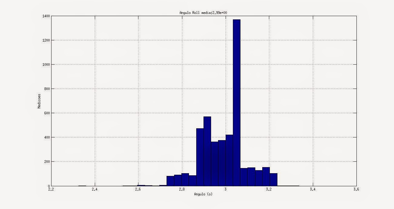
Os gráficos seguintes apresentam os valores de Pitch e Roll nas condições anteriormente descritas. Bem como a distribuição dos dados em histogramas.
 |

 |
| Figura 1: Dados obtidos para os ângulos com sistema horizontal e em repouso. |
Verifica-se para ambos os casos que a variação máxima de ângulo é de cerca de +- 0.5 graus.
Os resultados obtidos deste teste foram bastante bons e satisfatórios.
O objetivo do teste com o robô em movimento serve de comparação entre métodos, de modo a obter o método mais aproximado das variações de ângulo real, dado pelo Fanuc.
No entanto apenas vou apresentar a informação de um dos métodos, pelo que os valores obtidos por todos os métodos foi bastante similar.
Os gráficos seguintes apresentam o comportamento do Fanuc e dos sensores. O primeiro num movimento de ascendente e descendente. O segundo com variação de Pitch e depois de Roll.

 |
| Figura 2: Comportamento do Fanuc e leitura efetuada pelos sensores. |
Como resultado final deste teste obteve-se os gráficos da variação do ângulo de Pitch e de Roll relativamente ao lido no Fanuc.

 |
| Figura 3: Resultados obtidos na medição do pitch e do roll. |
Conclui-se assim que todos os métodos são válidos e têm todos eles bons resultados.
No entanto o método mais rápido e mais eficaz com o aumento do número de sensores é o método 3, pelo que este método não precisa de efetuar combinações para obter planos médios.
Por este motivo, este será o método a utilizar daqui em diante.
Todos os ficheiros relativos as medições dos sensores podem ser consultados aqui: ( download ).
-----
Eleventh and Twelfth Week :
Creation of a "real time" simulator for Fanuc robot in matlab.
The video contains the simulation results. The blue axes are the axes of robot "end effector". Is also represented the measurement made by the SHARP sensors. The green plane is the ground floor plane that sensors should detect. This plane is calculated based on the methods described in the last post.
By observing the video, we concluded that the sensors data were good and the calculation of the ground level was good too.
Two tests were also conducted. One test with the robot static and the other dinamic test.
The purpose of the static test is getting the measuremen error and get the horizontal plane to calibrate the system in the dinamic test.
The graphs in figure 1 show the values of Pitch and Roll in the static test and the data distribution in histograms.
It appears that in both cases the maximum angle variation is approximately + - 0.5 degrees.
The results of this test were quite good and satisfactory.
The purpose of the test with movement serves to compare methods and obtain the most approximate method of the orientations given by Fanuc.
However I will only present the information of one of the methods, because the values obtained by all methods were very similar.
The graphs in figure 2 show the behavior of Fanuc and sensors. First in a movement up and down. The second made variations on Pitch and Roll.
The results of this test are presented in figure 3. The variation of of pitch and roll are compared with Fanuc data.
We conclude that all methods are valid and all of them have good results.
However, the faster and more efficient was the third method.
For this reason, this will be the method to use.
All files related to the data processing can be consulted here: (download).


